Building a Bipedal Robot and Teaching it to Walk
I built a small bipedal robot and then had it train itself to walk.
The first gait I wrote by hand was a careful, halting shuffle that moved the robot at 0.35 cm/s. The hill climber optimizer was able to improve this to 0.91 cm/s - a 160% improvement. More importantly, the trained gait worked on the real robot.
This post walks through the whole project: how I chose the parts, how I designed and printed the body, and how I went from a hand-coded gait to a trained one.
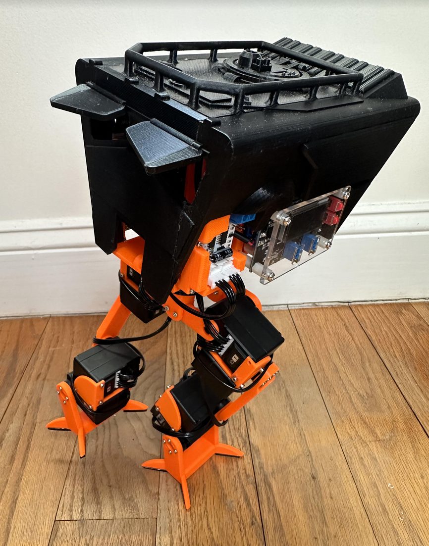
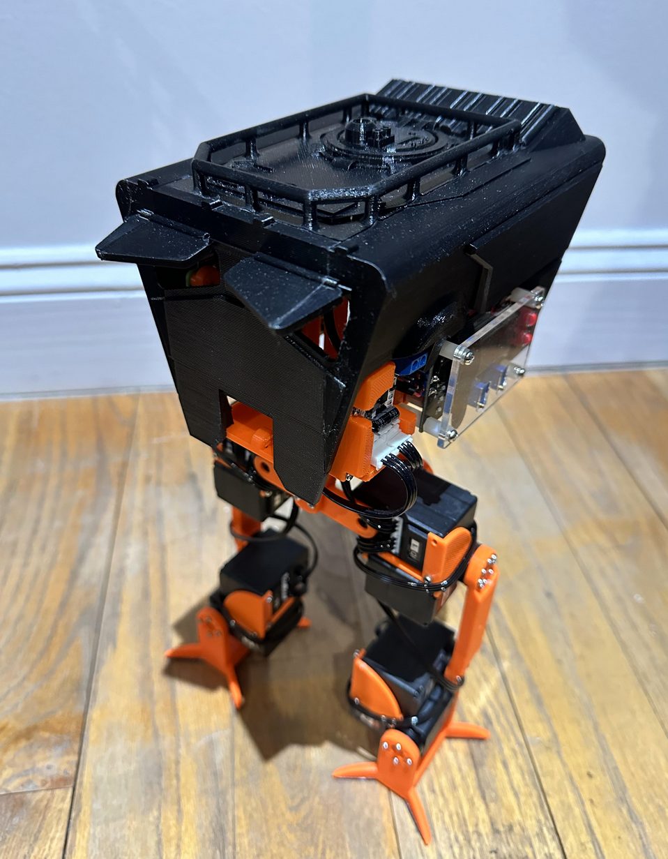 The finished robot. Roughly 35 cm tall, 900 g, eight motors.
Here is the final gait:
Picking a shape
Before any CAD, I sketched a few ideas to explore different designs.
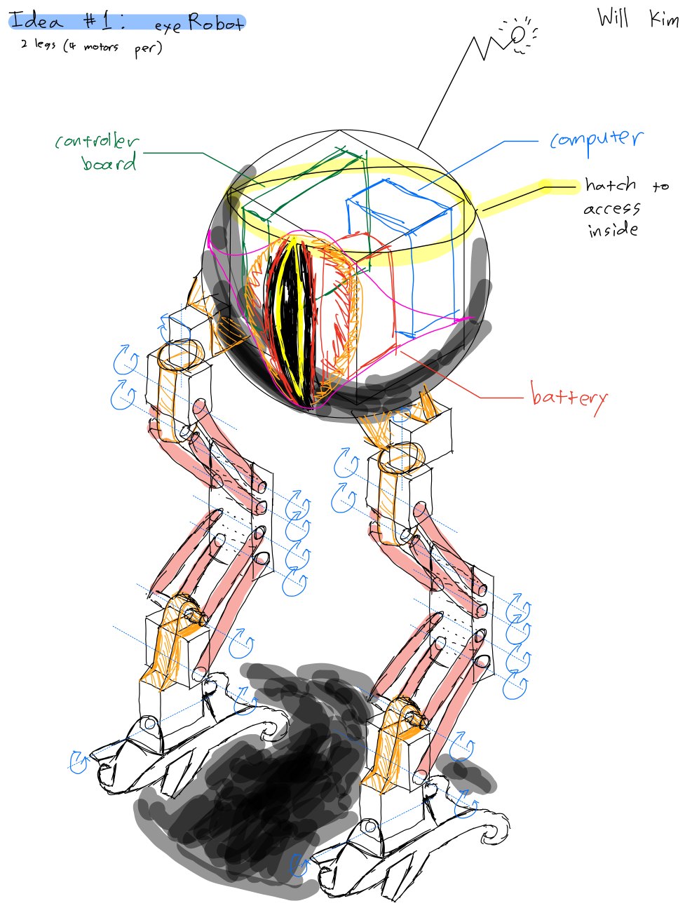 One of the early concepts. A round body on parallel-bar legs, with a knee that stayed level without its own motor.
The first idea used parallel-bar legs so the feet would stay flat to the ground without a dedicated knee motor. It looked great and saved a motor per leg, but the body sat high and the legs splayed wide, which is bad for balance.
The other two ideas were four-legged, because a quadruped is much easier to keep upright when it can always rest a stable base of feet on the ground. The first of them spread four legs out from a central body, with two motors per leg giving each foot its own yaw and pitch. The second lined all the motor axes up so the legs swung in a single plane, which traded away easy turning for more forward power in each step.
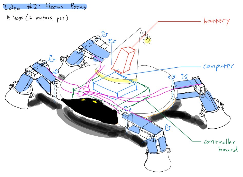 A four-legged concept with two motors on each leg, so each foot could yaw and pitch.
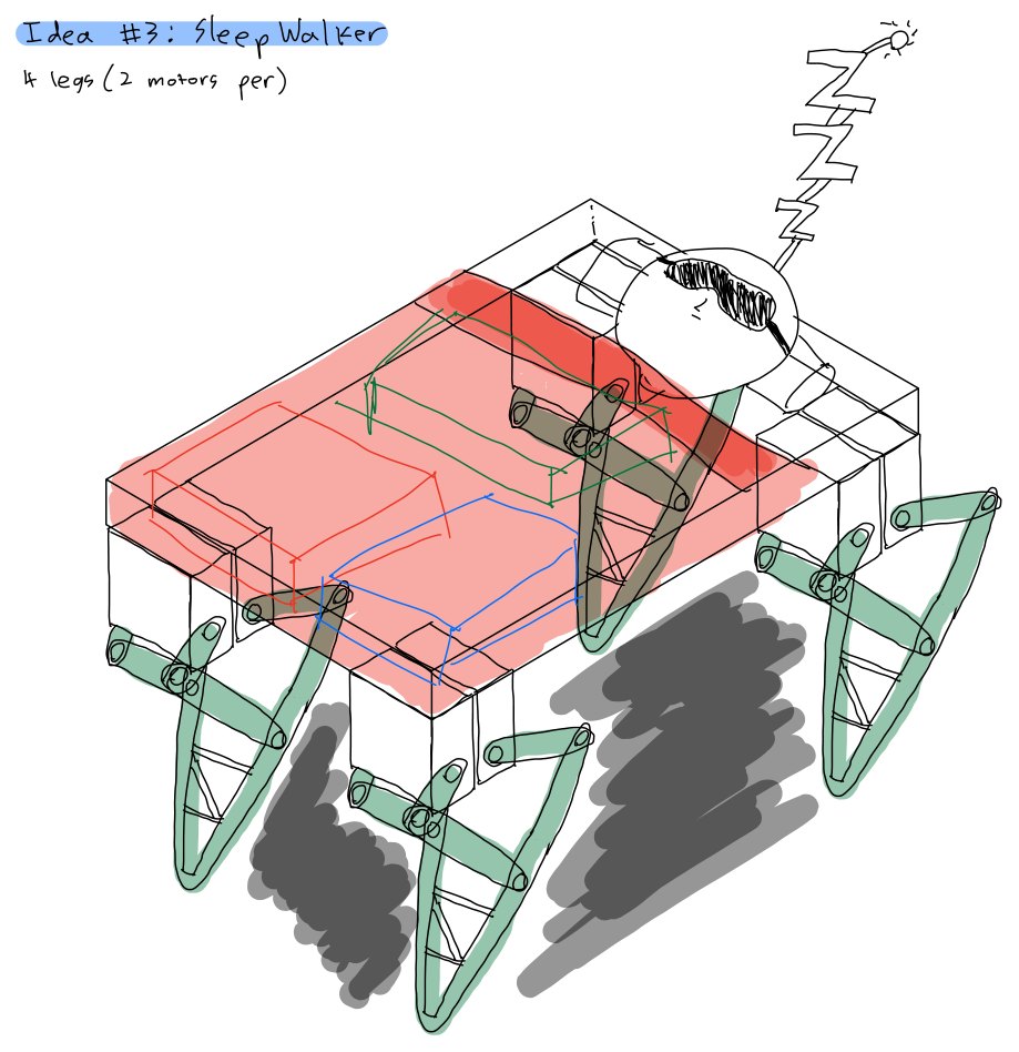 A second quadruped, with the motor axes aligned so the legs drove harder in one plane.
I went with a biped anyway, because a two-legged walker is a more interesting control problem.
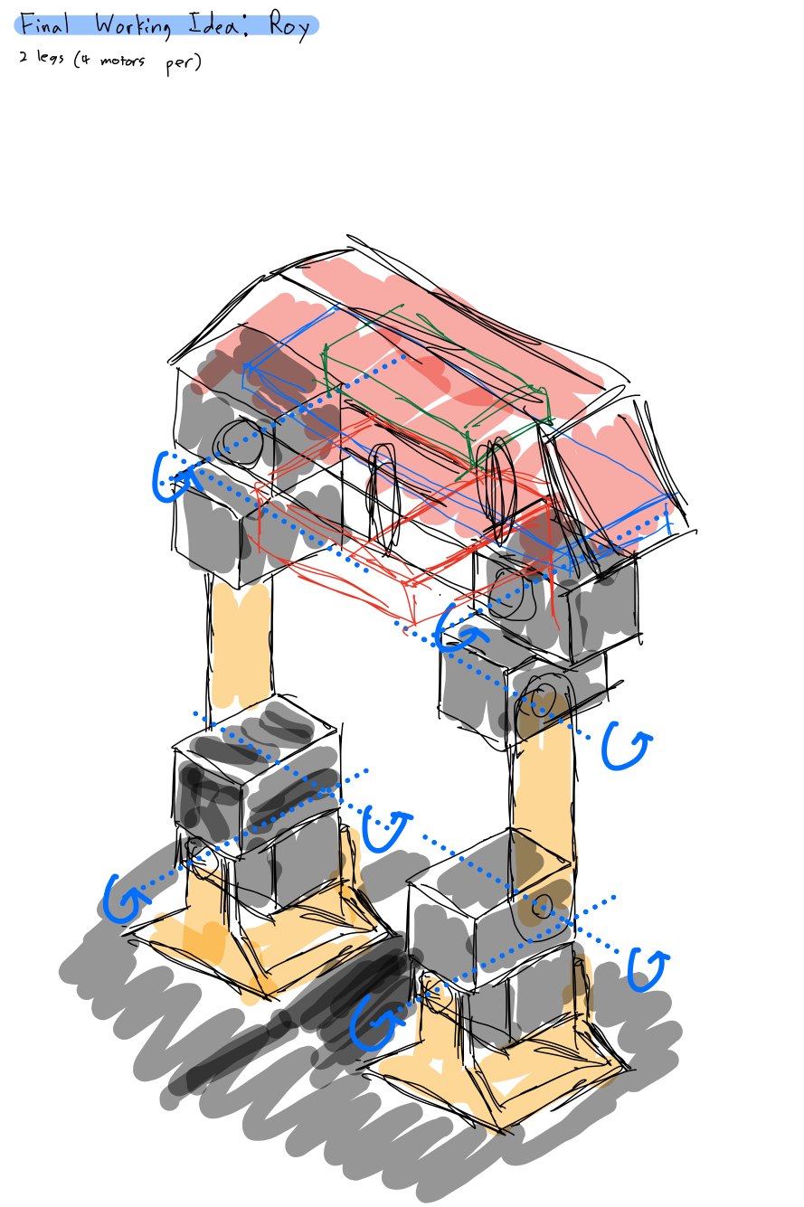 The design I committed to. Compact body, short legs, four powered joints per side.
In the end, I settled on the above design. I had to consider the torque requirements of the joints. The worst case for a biped is standing on one foot mid-step. At that instant, a single hip and ankle have to hold the entire robot up, and the further the mass sits from the joint, the more torque that takes. Shrinking the robot shortens the lever arms and lowers the mass, which shrinks the torque each motor has to supply. Rather than buy bigger, heavier, more expensive motors, I made the robot small enough that affordable servos had torque to spare. The final build came out around 35 cm tall and 900 g.
Choosing the components
The robot needed motors, a motor controller, an onboard computer, a battery, and a power converter. I treated each one as a requirement first and a part second.
| Component | Requirement | Choice |
|---|---|---|
| Motors | Precise, repeatable joint angles that hold position, with feedback, and enough torque to hold the robot on one leg | LewanSoul LX-16A serial bus servos |
| Motor control | Drive 8 motors without 8 separate control lines | Daisy-chained serial bus (built into the LX-16A) |
| Computer | Run Python, talk to the servo bus, allow headless development | Raspberry Pi 4 |
| Battery | Power the 7.4 V motors and the 5 V computer from one pack | TalentCell 12 V 3000 mAh (two outputs) |
| Power converter | Step 12 V down to 7.4 V, hold steady under load, isolate motor noise | DROK adjustable buck converter |
| Structure | Cheap, light, and fast to redesign | 3D-printed PLA |
A few of these are worth expanding, because the reasoning is the point.
Motors. A walking gait is a sequence of specific joint angles held and changed on a schedule, so I needed closed-loop position control, not the open-loop spin of a hobby DC motor. A servo holds a commanded angle and reports its actual position back. The servo also has to hold the robot up under static load, which brings torque back into the picture. The LX-16A is rated at 19.5 kg·cm at 7.4 V (17 kg·cm at 6 V), which clears the holding load of a sub-1 kg robot with comfortable margin. That margin is exactly what the “keep it small” decision bought me. The LX-16A also has a 240 degree range, metal gears that survive repeated loading, and real-time position feedback.
The serial bus. Eight motors driven by individual PWM lines is eight things to wire, route, and debug. The LX-16A motors daisy-chain on a single serial bus, so one data line addresses all eight by ID, and they came with their own controller board. That is far less wiring and far fewer failure points.
Battery and power. The TalentCell pack has two outputs that can be used at once, so a single battery powers both the motor rail and the Raspberry Pi. The motors want 7.4 V and the battery puts out 12 V, so the buck converter steps it down. It does two other jobs that matter more than the voltage math: it holds the output steady when the motors spike the current draw, and it buffers the sensitive computer and logic from the electrical noise the motors throw onto the line. I picked an adjustable one with a current and voltage display so I could tune and monitor it.
Building a leg, then the robot
I built one leg first and got it fully working before committing to the rest. A leg is comprised of a foot, two joints (each joint is two motors, one for roll and one for pitch), and a bar connecting them.
To model parts that bolt onto real motors, I measured the motors’ screw holes with calipers and built those dimensions into the CAD in SolidWorks. Two things drove every part: structural strength and printability. Sharp internal corners got fillets so they would not snap, and I avoided overhangs so the printer would not need support material everywhere.
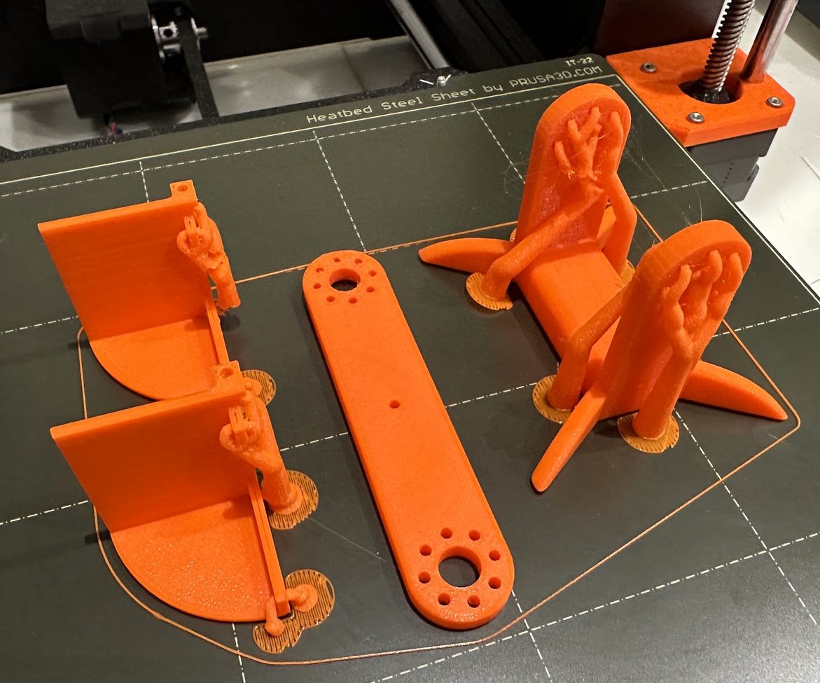 All the printed parts for one leg. The tree-like structures are supports that get cut away.
Printing taught the usual hard lessons. Screw holes and friction-fit joints need millimeter accuracy, and the printed dimensions never quite matched the model, so the first few of everything went in the reject pile. Once the tolerances were dialed in, a full leg’s parts batched into a single 12-hour print.
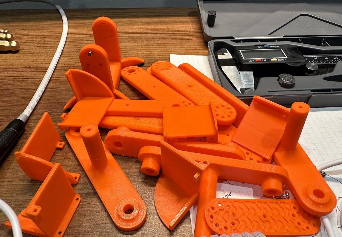 The trial-and-error pile. Failed prints and parts that came out a hair off from the model.
With a leg assembled, each motor had to be set up in software: confirm the wiring worked, give each motor a unique ID on the bus (they all ship as ID 1), and center each one at the middle of its range so it had room to rotate both ways. A public Python library for the LX-16A handled the low-level commands. Then I mirrored every part and built the second leg.
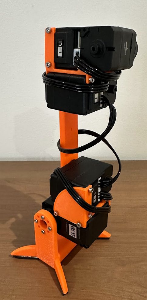 One finished leg, with rubber pads added to the foot for traction.
The torso came in two pieces: a “hip” that structurally joins the legs and holds the electronics, and a case that covers and protects them. The driving constraint was keeping the heavy parts low and centered. The battery is by far the heaviest component, so it sits dead center, oriented front-to-back to keep the side-to-side weight concentrated in the middle.
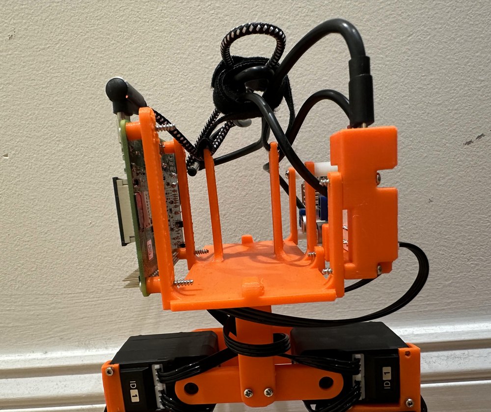 The hip platform from the front. The battery threads through the two central posts on a velcro strip, which holds it firm but lets me pull it out to charge.
The circuit boards are all flat, so the most compact layout was to sandwich them against the battery, one face on each side, with the sides chosen to keep cable runs short. The Raspberry Pi went on one side, and the motor hub and power converter on the other.
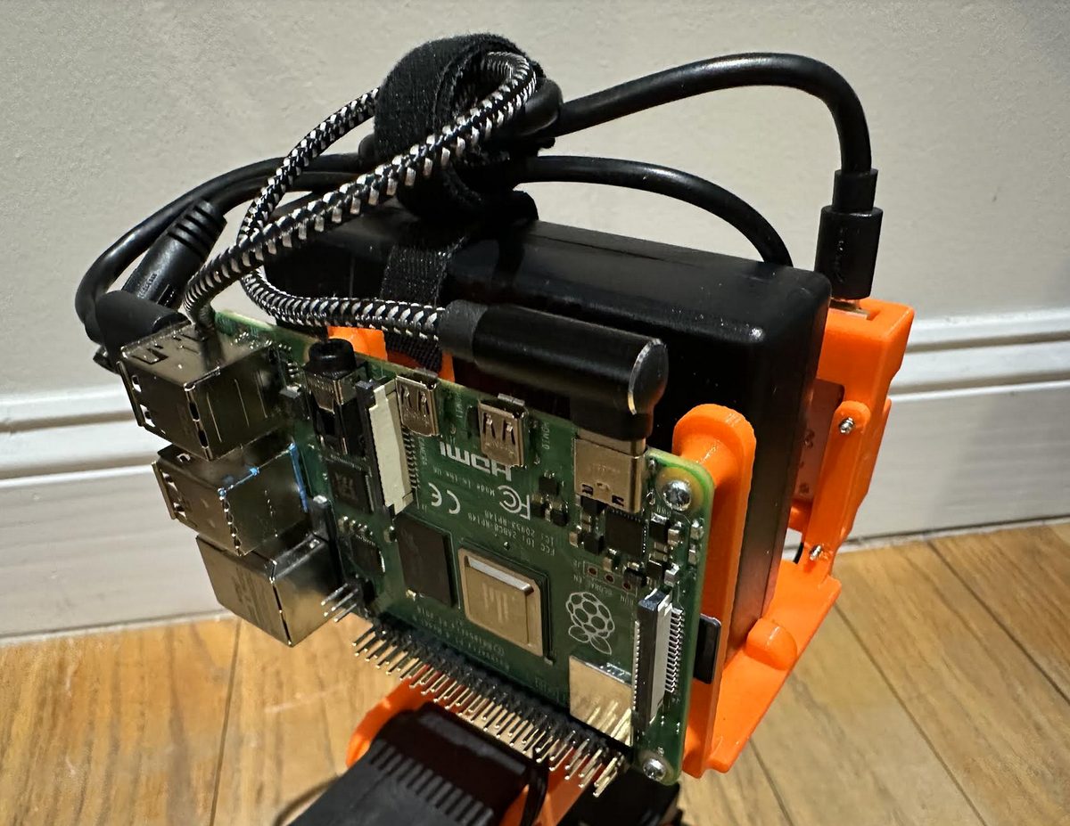 The right side, with the Raspberry Pi.
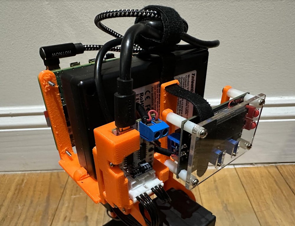 The left side, with the motor hub and the power converter (the blue terminal block).
The case went through three versions. The first did not account for the bulk of the cables and would not close. The second was a heavy, full shell that swallowed the whole body and took a full day to print, styled after the Gekko from Metal Gear. The third worked more like a roll cage than a full shell, which cut print time and weight and left the power converter visible, and I shaped it after the AT-ST walker from Star Wars.
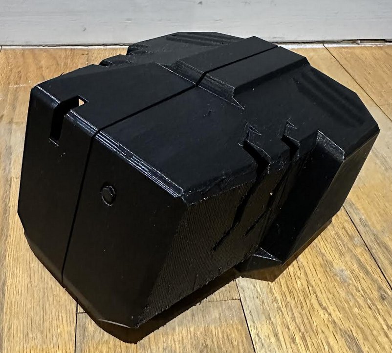 The Gekko-styled early shell. It looked the part but was heavy and slow to print, so the final design opened it up into the AT-ST roll cage.
The legs needed revisions too. They flexed too much when the robot stood on one foot, so I thickened them and reprinted with denser infill, and they sometimes jammed on the motor screws, so I cut more clearance into them. I also tried bracing each leg with an extra printed column. It did stiffen them, but it cut into the hip motors’ range of motion enough that I dropped the idea.
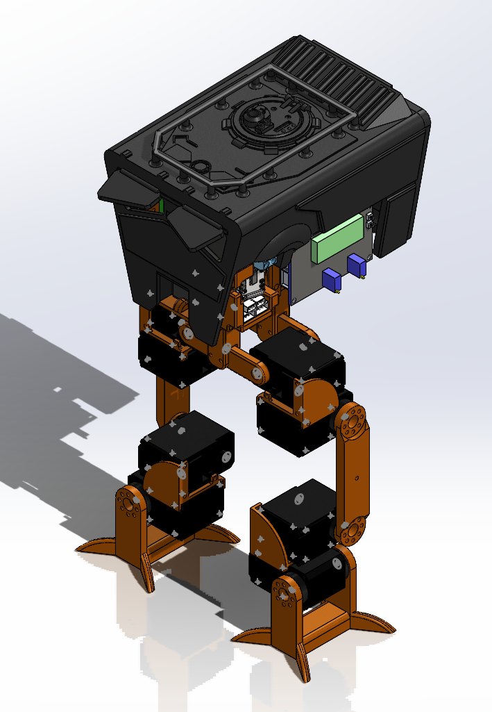 The CAD model and the physical build. Keeping them in sync mattered later, because the model became the simulation.
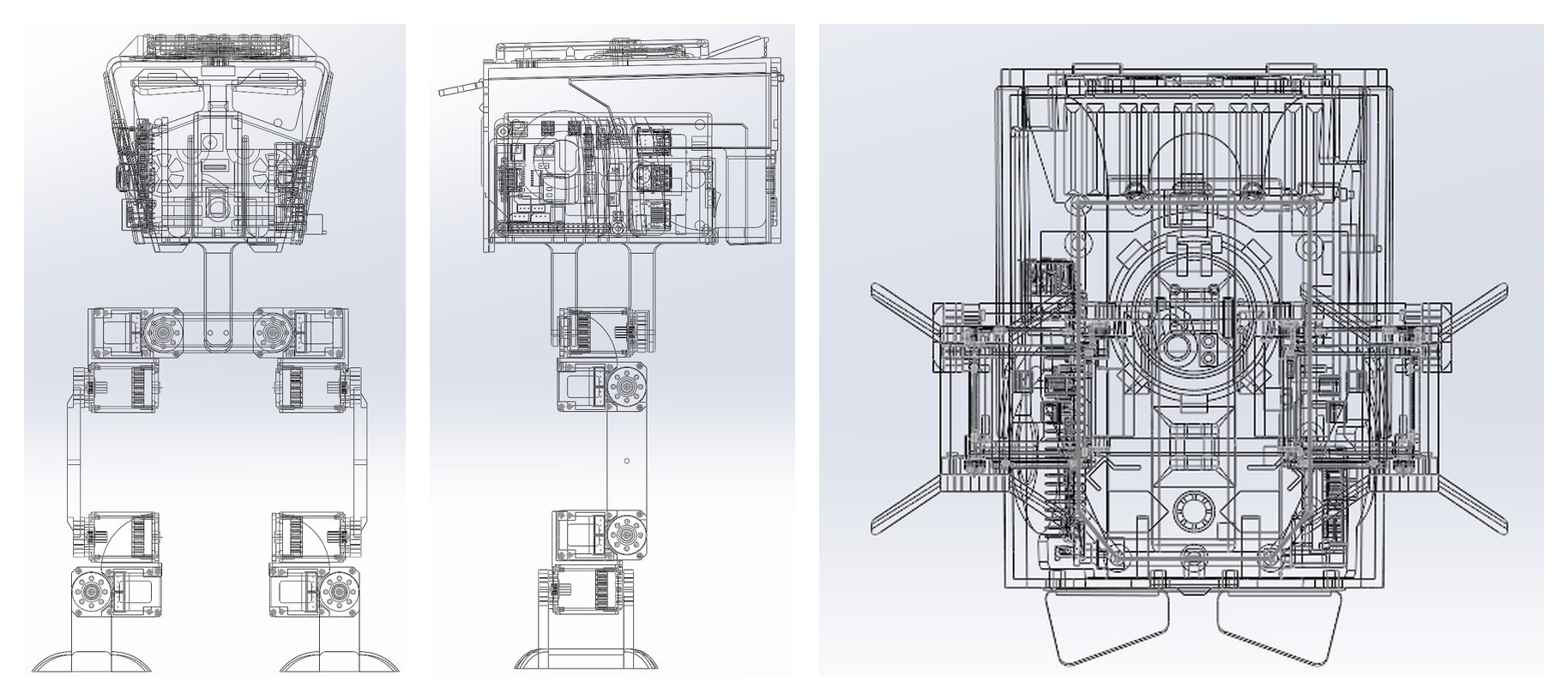 Front, right, and top views of the model. Every part was assembled here with its real material properties, which is what made the later simulation accurate.
Teaching it to walk, by hand
The most direct way to get it moving was to imagine an efficient walk cycle and program it in. I made this first gait statically stable, meaning that if the robot froze at any point in the cycle, it would stay standing. This is less efficient than how a human walks, but it is forgiving and the code is simple.
I broke the cycle into three moves in sequence: shift weight onto one leg, swing the other leg forward, then shift onto the leg that just moved. Each move turned up a real constraint. My first weight-shift kept the torso level by rotating the hip and ankle together, which works at speed because momentum carries the robot onto one foot. At the slow speeds a statically stable walk needs, momentum is not there to help, and the free foot would not leave the ground. The fix was to rotate that foot outward to lift it.
The swing-forward move ran into the hardest limit. With no knee joint, the legs are a fixed length, so the robot could only reach so far forward before its center of mass passed the planted foot and it tipped. I tried leaning back on the planted leg to reach further, but without a knee there was no way to change leg length to make that work. I noted those ideas for later and moved on.
The result was 0.35 cm/s, stable but slow and halting, and clearly leaving speed on the table. Tuning it further by hand on real hardware would have been painfully slow, so I moved to simulation.
Building the simulator
Real-world tuning is slow because every change means re-flashing the robot and watching one attempt. A simulation can run thousands of attempts unattended, and a deterministic one lets me reproduce a good run exactly to study it. So I rebuilt the robot in software.
The model became a URDF, the standard XML format for describing a robot’s links, joints, axes, and physical properties like mass and moments of inertia. I then loaded that URDF into PyBullet, an open-source physics engine with good documentation, a deterministic core, and a graphics window for actually watching the robot.
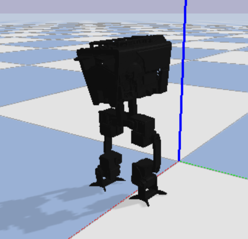 The robot rebuilt as a URDF and dropped into the PyBullet simulator.
Creating the URDF was a slight headache. I had built the original model with the Y axis pointing up, but URDF expects Z up. Remapping the axes should have been a quick fix, except some features in the model were defined relative to global axes and others were defined relative to those features, so changing one broke the next. Small edits cascaded into half the model falling apart. In the end the SolidWorks URDF exporter handled the conversion, but I noted to myself that in the future, I should lock exactly one parent component to a global coordinate frame, and define everything else relative to that.
The optimizer
Instead of scripting the gait as a list of poses, I drove every motor with a sine wave. Each of the eight motors follows the same shape:
M = offset + amplitude * sin(omega * t + phase)
The offset sets the joint’s neutral angle, the amplitude sets how far it swings, omega sets the step frequency, and phase shifts motors relative to each other so the legs coordinate. Pick those numbers well and you get a walk. The whole gait is just a handful of parameters.
That framing turns “find a good gait” into “find good numbers,” which is something a computer can search. I used a hill climber, which is about the simplest optimizer there is. Start from a known-decent set of parameters, nudge them randomly, keep the nudge only if it made things better, and repeat that loop over and over. I seeded it with parameters that mimicked my hand-coded walk, so it started from something that already worked. Here is the core of it, trimmed from the real script:
# nudge a value up or down by up to 2%
def mutate_value(original_value):
    random_factor = choice([0.98, 0.99, 1, 1.01, 1.02])
    return original_value * random_factor

for j in range(1000000):
    # mutate every parameter, then run the gait in the sim
    a0t, a3t = mutate_value(a0), mutate_value(a3)
    b0t, b3t = mutate_value(b0), mutate_value(b3)
    b1t, b5t = mutate_value(b1), mutate_value(b5)
    wt = mutate_value(w)

    for i in range(15000):
        p.stepSimulation()
        # drive the 8 joints from the sine-wave gait
        p.setJointMotorControl2(robotId, 0, mode, targetPosition=a0t + b0t * sin(wt * i))
        # ... seven more joints ...

        # bail out early if the robot falls, veers, or lurches
        pos, orn = p.getBasePositionAndOrientation(robotId)
        if abs(orn[0]) > .55 or abs(orn[1]) > .55 or abs(orn[2]) > .1 or abs(pos[1]) > 0.2:
            break

    # keep the mutation only if it walked farther forward
    pos, orn = p.getBasePositionAndOrientation(robotId)
    if distanceTravelled < pos[0]:
        distanceTravelled = pos[0]
        a0, a3, b0, b1, b3, b5, w = a0t, a3t, b0t, b1t, b3t, b5t, wt
The bail-out condition matters as much as the reward. Judging a run only by distance is not enough, because the optimizer is happy to cheat. My first runs produced a gait that dragged the feet along the ground, which the rubber-padded real feet could never do. So I cranked the simulated friction up to discourage dragging, and I tossed any run where the robot fell over, veered off course, or accelerated too hard. Shaping what counts as “better” was a fun part of the process.
The local minimum problem
A hill climber has a famous weakness. Because it only ever accepts changes that improve the current gait, it can climb to the top of a small hill and get stuck there, with no way to reach a taller hill across the valley, because getting there means going downhill first. Think of a ball dropped on a bumpy field. It settles into whatever dip it happens to land near, and that dip is rarely the deepest one on the field. That is why seeding the search from a gait that already works matters so much. The closer you start to a good solution, the better your odds of climbing the right hill.
Cutting the search down
The hill climber stalled when there were too many parameters, because it mutated all of them at once, and improvements that needed only one or two specific changes were rare to stumble into, so I shrank the problem.
I started with 25 parameters and got it down to 7 by exploiting symmetries in the gait. All the side-to-side motions share a phase, so four phase values collapse to one, and the same holds for the forward-and-back motions. Those two phases then collapse to one by fixing the offset between them at a quarter cycle, on the logic that a step peaks just as the robot is halfway through shifting its weight. That quarter-cycle offset is why the roll motors end up driven by a sine and the pitch motors by a cosine. Mirroring the left and right timing and dropping redundant offsets cleared out the rest, and what remained was seven numbers driving all eight motors:
left hip roll    =  a0 + b0*sin(w*t)        right hip roll    = -a0 + b0*sin(w*t)
left ankle roll  =  a3 + b3*sin(w*t)        right ankle roll  = -a3 + b3*sin(w*t)
left hip pitch   =  b1*cos(w*t)             right hip pitch   =  b5*cos(w*t)
left ankle pitch = -b1*cos(w*t)             right ankle pitch = -b5*cos(w*t)
That is a roll offset and amplitude for the hips and ankles (a0, b0, a3, b3), a step-size amplitude for each leg (b1, b5), and the shared step frequency (w). Seven parameters is a search a hill climber can actually handle, and after about 100,000 runs it produced a stable gait at 0.42 cm/s.
The table below is the optimizer’s own output. What I like about it is the last column, where each abstract number maps to a physical change in how the robot moves.
| Parameter | Role | Change | Effect on the walk |
|---|---|---|---|
| α₀ | hip roll offset | +15% | legs drawn closer together, less wobble when shifting side to side |
| β₀ | hip roll amplitude | +185% | keeps the torso level |
| β₃ | ankle roll amplitude | +142% | leans harder to put the center of mass over the planted foot, more stable |
| β₁ | left step size | −47% | shorter left step |
| ω | step frequency | +25% | faster steps |
One more push
At 0.42 cm/s the gait was stable but still gentle. Two things make a walker faster: longer steps or quicker steps. Both have a ceiling. Steps can only get so quick before the robot tips sideways, and so long before its mass runs past the planted foot. A faster walk lives in nudging both up together.
Here the optimizer needed a shove. A hill climber will not make a big stylistic leap on its own, because the intermediate gaits are worse and it refuses to go through them. So I re-seeded it with parameters that exaggerated step size and frequency, pointing it at the kind of gait I wanted, and let it optimize from there. That worked: the lateral sway shrank, the steps grew, and the robot reached 0.91 cm/s, a 160% improvement over the hand-coded walk. The new gait also looked more natural, with less wasted side-to-side motion.
The final gait landed on these seven values:
a0 = a3 = 0.155      b0 = 0.11      b3 = 0.155
b1 = b5 = -0.21      w  = 0.013
Here is that gait. The viewer loads the robot’s real URDF and replays the walk by plugging those numbers into the same eight equations on a clock, one angle per joint per frame. Press Walk, then drag to look at it from any angle.
Sim to real
The payoff was that the gait trained entirely in an idealized simulation still worked when I loaded it onto the actual robot, and there was no guarantee of that. Simulations get friction, mass, and timing slightly wrong, and gaits often fall apart on contact with reality, but this one held up.
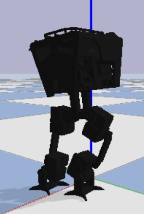 The trained gait in the simulator, mid-step.
 The same gait running on the hardware.
Despite this success, it was clear to me that the robot was not operating at the peak of its physical capability. The robot never left the fully actuated regime of movement, and did not explore faster, underactuated gaits. Part of this came from the way I set up its motion. A sum of sine waves cannot pause a motor mid-cycle (unless I add many more terms to the equations of motion - but this again runs into the issue of high dimensionality), and the best possible gait might want exactly that. The natural next step is an open-ended evolutionary approach that does not start from a fixed equation, so it can discover motions a few sine waves cannot describe.
Takeaways
The build pulled together a lot of disciplines, from mechanical design and manufacturing through electronics, physics simulation, and the optimization itself, and two lessons stuck with me more than the rest.
The first is that good optimization is mostly good problem framing. The hill climber itself is about as simple as an algorithm gets, and it barely changed across the whole project. Almost all of the work went into the parts around it: describing the gait as a few parameters, shrinking that set with symmetry until the search could move, shaping the reward so the robot could not cheat its way to a high score, and seeding the search somewhere close enough to a good answer to actually reach one.
The second is that early decisions quietly set the terms for everything after them. Choosing a small robot fixed the torque budget, which fixed the motor, which fixed how the wiring had to work, and building the CAD model carelessly cost me days once that same model became the simulation.